Principles of operation
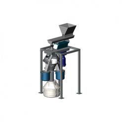
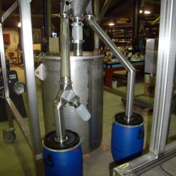
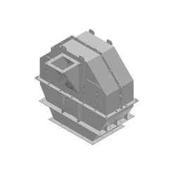
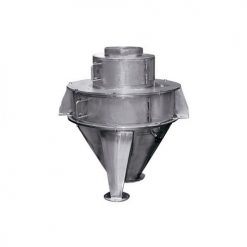
The Rotary Tube Divider Motorised Flaps (PDMF) is designed for representative dividing of bulk material. The PDMF is a special version of the Rotary Tube Divider (PD) and is equipped with an automated sample size adjustment feature.
Find info on the standard machine within our PD brochure.
Download PD Divider Motorized Flap(S) brochure (PDF)Description of motorized flaps
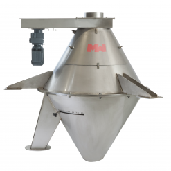
One or two slot adjustment drive units are placed on the outside of the discharge cone.
The unit consists of a geared motor mounted on the discharge cone, which through a gear drives the flap plate by engaging an arced gear rack connected to the flap plate.
The movement of the flap plate is adjusted from the control room/cabinet and the desired division ratio is achieved quickly.
A limit switch in each end position will stop the movement and inform whether the damper is fully closed or fully open.
Technical data
| Drive unit: | Geared motor |
| Voltage: | 400/230V-50Hz or as required |
| Sensor: | Motion detector Potentiometer Limit switches |
| Dimensions: | Refer to drawing and table |
Drawing
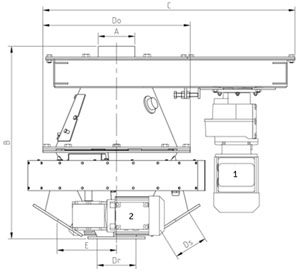
Type designation:
The values are only indicative
| Type | Particle size [mm] | øA [mm] | B [mm] | C [mm] | øDO [mm] | ds [mm] | Ødr [mm] | E [mm] | Motor 1 [kW] | Motor 2 [kW] | Tube speed [rpm] | Division circum-fer-ence [mm] |
| PD8/100 | 25 | 100 | 535 | 705 | 410 | 60×60 | 100 | 170 | 0.25 | 0.09 | 44 | 825 |
| PD12/100 | 35 | 100 | 790 | 1045 | 640 | 60×60 | 200 | 290 | 0.25 | 0.09 | 29 | 1255 |
| PD12/200 | 40 | 200 | 790 | 1045 | 640 | 150×150 | 200 | 290 | 0.25 | 0.09 | 29 | 1255 |
| PD17/100 | 35 | 100 | 1015 | 1095 | 740 | 100×100 | 200 | 330 | 0.37 | 0.09 | 21 | 1720 |
| PD17/200 | 50 | 200 | 1015 | 1095 | 740 | 150×150 | 200 | 330 | 0.37 | 0.09 | 21 | 1720 |
| PD27/100 | 35 | 100 | 1535 | 1370 | 1200 | 100×100 | 200 | 600 | 0.55 | 0.09 | 13 | 2700 |
| PD27/200 | 65 | 200 | 1535 | 1370 | 1200 | 150×150 | 200 | 600 | 0.55 | 0.09 | 13 | 2700 |