Principles of operation
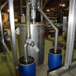
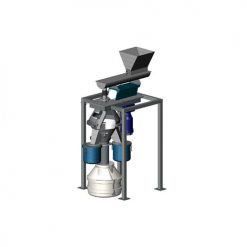
The Disc Divider (DD) is used for dosing and dividing of bulk material. A representative sample is ensured by a continuous automatic division.
Download Disc Divider brochure (PDF)Description of motorized flaps
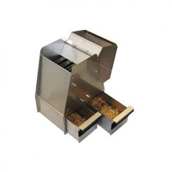
The material is fed to the Disc Divider through the top section, where the material is scraped off the upper disc down to the lower disc. Here, the material is scraped down to the bottom section, where the slot opening(s) extract(s) a quantity corresponding to its width and the rest passes into the reject outlet. The division ratio is stepless adjusted between 1:9 and 1:56 –dependent of DD model and particle size.
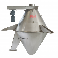
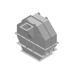
The Disc Divider is manufactured of stainless steel and essentially consists of the following units:
- Top section: The upper disc and two scrapers.
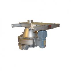
- Middle section: Lower disc, drive unit and the rotor which is connected to the above mentioned scrapers.
- Bottom section: Cone with one or more adjustable sample outlet(s) and reject outlet.
- Inspection hatches for easy access.
Technical data
| Drive unit: | Geared motor |
| Voltage: | 400/230V-50Hz or as required |
| Sensor: | Motion detector |
| Dimensions: | Refer to drawing and table |
Drawing

Type designation:
The values are only indicative
| Type | Particle size [mm] | øA[mm] | B[mm] | C[mm] | øDO[mm] | ds[mm] | ØDr[mm] | E[mm] | Motor[kW] | Division circum- ference[mm] | Shaft speed[rpm] | Weight[kg] |
| DD12 | 15 | 200 | 700 | 1045 | 640 | 60×60 | 200 | 290 | 0.25 | 1255 | 29 | 70 |
| DD17 | 20 | 200 | 900 | 1095 | 740 | 150×150 | 200 | 330 | 0.37 | 1270 | 21 | 120 |